- Гідрологія і Гідрометрія
- Господарське право
- Економіка будівництва
- Економіка природокористування
- Економічна теорія
- Земельне право
- Історія України
- Кримінально виконавче право
- Медична радіологія
- Методи аналізу
- Міжнародне приватне право
- Міжнародний маркетинг
- Основи екології
- Предмет Політологія
- Соціальне страхування
- Технічні засоби організації дорожнього руху
- Товарознавство продовольчих товарів
Тлумачний словник
Авто
Автоматизація
Архітектура
Астрономія
Аудит
Біологія
Будівництво
Бухгалтерія
Винахідництво
Виробництво
Військова справа
Генетика
Географія
Геологія
Господарство
Держава
Дім
Екологія
Економетрика
Економіка
Електроніка
Журналістика та ЗМІ
Зв'язок
Іноземні мови
Інформатика
Історія
Комп'ютери
Креслення
Кулінарія
Культура
Лексикологія
Література
Логіка
Маркетинг
Математика
Машинобудування
Медицина
Менеджмент
Метали і Зварювання
Механіка
Мистецтво
Музика
Населення
Освіта
Охорона безпеки життя
Охорона Праці
Педагогіка
Політика
Право
Програмування
Промисловість
Психологія
Радіо
Регилия
Соціологія
Спорт
Стандартизація
Технології
Торгівля
Туризм
Фізика
Фізіологія
Філософія
Фінанси
Хімія
Юриспунденкция
Important Definitions
Attenuation to Crosstalk Ratio (ACR)
A critical consideration in determining the capability of an unshielded twisted-pair (UTP) or screened twisted-pair (ScTP) cabling system is the difference between attenuation and near-end crosstalk (NEXT). This difference is known as the attenuation to crosstalk ratio (ACR). Positive ACR means that transmitted signal strength is stronger than that of near-end crosstalk. ACR helps to define a signal bandwidth (i.e. 200 MHz for category 6) where signal to noise ratios are sufficient to support certain applications. It is interesting to note that digital signal processing (DSP) technology can perform crosstalk cancellation allowing some applications to expand useable bandwidth up to and beyond the point at which ACR equals zero. Even so, the maximum frequency for which positive ACR is assured provides a benchmark to assess the useable bandwidth of twisted-pair (balanced) cabling systems.
Attenuation
Attenuation is a measure of the decrease in signal strength along the length of a transmission line. Ensuring low signal attenuation is critical because digital signal processing technology can not compensate for too much signal attenuation.
Near-End Crosstalk (NEXT)
and Equal Level Far-End Crosstalk (ELFEXT)
Pair-to-pair near-end crosstalk (NEXT) requirements quantify undesired signal coupling from adjacent pairs that is received at the same end of the cabling as the transmit end of the disturbing pairs. Standards groups now realize that the sophisticated nature of full-duplex transmission will also require that the crosstalk at the far-end of the cabling be specified. Pair-to-pair far-end crosstalk (FEXT) quantifies undesired signal coupling at the receive end of the disturbing pairs. ELFEXT is calculated by subtracting attenuation from the far-end crosstalk loss. Poor ELFEXT levels can result in increased bit error rates and/or undeliverable signal packets. Note that NEXT margin alone is not sufficient to ensure proper far-end crosstalk performance!
Power Sum
Power sum NEXT and ELFEXT performance provides headroom to ensure cabling channels are significantly robust to handle crosstalk from multiple disturbers. Power summation accounts for the combined performance of all pair combinations. This type of characterization is needed to ensure cabling compatibility with applications that utilize all four pairs for transmitting and receiving signals simultaneously (e.g. Gigabit Ethernet).
Return Loss
Return loss is a measure of the signal reflections occurring along a transmission line and is related to impedance mismatches that are present throughout a cabling channel. Because emerging applications such as Gigabit Ethernet rely on a full duplex transmission encoding scheme (transmit and receive signals are superimposed over the same conductor pair), they are sensitive to errors that may result from marginal return loss performance.
Propagation Delay & Delay Skew
Propagation delay is equivalent to the amount of time that passes between when a signal is transmitted and when it is received at the other end of a cabling channel. The effect is akin to the delay in time between when lightning strikes and thunder is heard - except that electrical signals travel much faster than sound. Delay skew is the difference between the pair with the least delay and the pair with the most delay. Transmission errors that are associated with excessive delay and delay skew include increased jitter and bit error rates.
Bandwidth (fiber)
Bandwidth describes the frequency carrying capabilities of a transmission system and is a function of fiber type, distance, and transmitter characteristics. Bandwidth margin maximizes a system's ability to support advanced applications.
Balance
Twisted-pair transmission relies on signal symmetry or "balance" between the two conductors in a pair. Maintaining proper balance ensures that cabling systems and components do not emit unwanted electromagnetic radiation and are not susceptible to electrical noise. Although these parameters are not industry requirements, it is recommended that the balance performance of cabling components be ensured through measurements of longitudinal conversion loss (LCL) and longitudinal conversion transfer loss (LCTL).
Transfer Impedance
Shield effectiveness directly affects the ability of shielded twisted-pair cable and connecting hardware to maximize immunity from outside noise sources and minimize radiated emissions. Transfer impedance is a measure of shield effectiveness; lower transfer impedance values correlate to better shield effectiveness.
Survivability:
Protecting The Passives
By Lou Maiolo for The Siemon Company
Often overlooked, the protection of fiber optic patchcords is essential to the survival of the network. A kink or severe bend in a fiber optic patchcord can result in unacceptable attenuation and eventually a lost signal. Lost signals equate to lost revenue. One of the Long Distance Companies shared the information listed in Table #1 with me. This table tells us that a typical "transaction" (e.g. conversation) requires 56,000 bits. The Long Distance Provider claimed that his company's typical transmission is 2.5 Gigabit. This equates to approximately 45,000 transactions per minute. Add in transmission using an 8 channel WDM and now we are transmitting 360,000 transactions per minute. Using $0.20 per minute as a revenue rate, this translates to $72,000 per minute in potential lost revenue when a signal is lost!
| 56,000 Bits per transaction 2.5 Gig typical transaction today = approx 45,000 transactions per wavelength w/8 channel WDM = 360,000 transactions @ $0.20 per minute |
| Table 1 |
So how do you protect your fibers? Before routing any patchcords, strongly consider a Fiber Protection System (FPS) for housing these patchcords. A properly designed (and installed) FPS will protect your fiber network by ensuring that proper fiber bend radius is maintained. A proper FPS will also provide for accessibility to your fiber cables now, and in the future as you expand the network.
Here are some helpful tips on FPS selection and use.
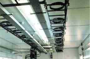 Figure 1: Don't latch fibers to ladder racking. Figure 1: Don't latch fibers to ladder racking.
| Protect Your Fiber:Don't latch it to ladderracking, it may attenuate. Methods and procedures followed for coax or copper cables just don't apply to fiber optic cables. Coax and copper cables typically won't attenuate when latched to ladder racking (figure #1). Fiber Optic cables, however, are delicate. Latching can squeeze the fiber inside creating macro bends resulting in light loss and signal degradation. | |
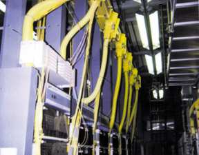
Protect Your Fiber: Fiber Cables are indeed delicate. Weaving your way through a "spaghetti bowl" of tangled fiber optic cables is surely one way to break a fiber. Part of protecting the fiber cables involves making them accessible. When fiber protection systems (FPS) or ducting is used (which should be always), it should be installed low enough from the ceiling to permit accessibility inside. In figure #2, the FPS has been placed up against the ceiling making accessibility difficult. Additionally, this user has selected an FPS which has "fingers" in lieu of solid walls. A lazy or uneducated installer has used the finger retainers as a means to coil storage loops. As these "fingers" have no radius control for the fiber cables, attenuation is sure to occur, if it hasn't already. |
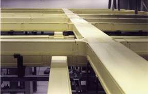
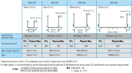
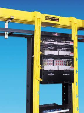
Durability: All too often, price is the governing factor when selecting a FPS. Some FPSs are cheaply priced, but just aren't durable enough to hold the weight typical of large central office fiber deployment. The last thing that you want to happen is buying a cheaper FPS that sags under load from fiber patchcords. A durable 8' wide FPS (the ideal size for large central office applications with a capacity of 2400 patchcords) should be able to hold over 50 pounds over a 6 foot span without sagging (figure #3)*. Before selecting a FPS, estimate the number of fiber patchcords that you will be installing at the site when at full capacity. Next, ask your FPS supplier for a chart showing patchcord capacity and weight capacity by FPS size. |
|
| Figure 4 |
Ease of Assembly: When selecting a FPS, calculate total installed cost rather than just the cost of materials. You may find that some low material cost FPSs will cost more in the long run after installation labor is factored into the equation. Hardware-laden FPSs can take over 50 hours to install for a typical 20' x 20' square horizontal run with a dozen vertical drops. This same installation could be accomplished in less than 24 hours with a snap-together system such as the LightWays&153 FPS offered by The Siemon Company (figure #5). This labor savings could amount to thousands of dollars for this particular example. Always calculate total installed cost (material and labor) rather than just material cost. |

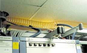
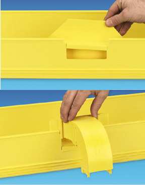
Ease of Use: Most FPS systems recommend the use of tubing to protect and route fiber cables in the horizontal to vertical transition. These flexible tubes may not be a problem initially when fiber patchcords are threaded through them. But adding patchcords at a later date can be difficult as these tubes can be clogged and congested. Threading patchcords through these tubes can cause unwanted strain on fiber connectors and, in some cases, cause fiber breakage. In some installations that we visited, tubes had become so congested that patchcords making horizontal to vertical transitions actually bypassed the tubes, hanging in the air unprotected (figure #6). An "open channel" system, where patchcords can be layed into the FPS rather than threaded through tubing, does a much better job of providing accessibility to patchcords installed in the FPS, and of accommodating future growth (figure #7). |
| Figure 7: LightWays™ "open channel" system. |
Ease of Expansion: One of the most dangerous procedures can be to add another horizontal path (tee) or vertical drop to an existing FPS which has patchcords already installed inside. Most FPSs require (1) elevating (moving) "live" fiber cables so that an FPS section can be removed (cut out with a saw) and (3) a horizontal tee or vertical downspout can be fastened to the existing structure with hardware. These three steps must be handled with extreme care, especially when moving "live" fibers. Frequently, this operation must be conducted on "off-peak" hours (eg. 12 midnight - 6:00AM) so as to minimize revenue loss/customer inconvenience should a fiber break or disconnection occur. Installer time can be expensive and difficult to contract at these off-peak hours. |
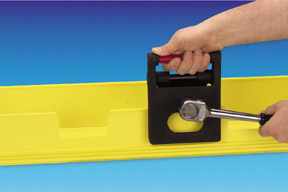
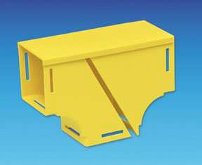
The Siemon Company's LightWays™ FPS offers a simple alternative method of expansion whereby "live" fibers need not be moved, and no assembly or disassembly of hardware is required. A unique cut-out tool removes a section of the FPS wall precisely where the horizontal expansion or vertical drop is to be added (figure #9). A breakout kit or vertical drop kit is then snapped into place, requiring no hardware (figure #8). Expansion of the original FPS is performed safer, and much faster (less than 5 minutes total) than other FPS systems. |
|
| <== попередня сторінка | | | наступна сторінка ==> |
| Category 7/Class F | | | Go back and fix it: Retrofits. |
|
Не знайшли потрібну інформацію? Скористайтесь пошуком google: |
© studopedia.com.ua При використанні або копіюванні матеріалів пряме посилання на сайт обов'язкове. |