- Гідрологія і Гідрометрія
- Господарське право
- Економіка будівництва
- Економіка природокористування
- Економічна теорія
- Земельне право
- Історія України
- Кримінально виконавче право
- Медична радіологія
- Методи аналізу
- Міжнародне приватне право
- Міжнародний маркетинг
- Основи екології
- Предмет Політологія
- Соціальне страхування
- Технічні засоби організації дорожнього руху
- Товарознавство продовольчих товарів
Тлумачний словник
Авто
Автоматизація
Архітектура
Астрономія
Аудит
Біологія
Будівництво
Бухгалтерія
Винахідництво
Виробництво
Військова справа
Генетика
Географія
Геологія
Господарство
Держава
Дім
Екологія
Економетрика
Економіка
Електроніка
Журналістика та ЗМІ
Зв'язок
Іноземні мови
Інформатика
Історія
Комп'ютери
Креслення
Кулінарія
Культура
Лексикологія
Література
Логіка
Маркетинг
Математика
Машинобудування
Медицина
Менеджмент
Метали і Зварювання
Механіка
Мистецтво
Музика
Населення
Освіта
Охорона безпеки життя
Охорона Праці
Педагогіка
Політика
Право
Програмування
Промисловість
Психологія
Радіо
Регилия
Соціологія
Спорт
Стандартизація
Технології
Торгівля
Туризм
Фізика
Фізіологія
Філософія
Фінанси
Хімія
Юриспунденкция
Introduction. Transmission line theory
Electromagnetic energy, once generated in one place, has a natural tendency to spread in the whole space at a speed close to 300.000 Km/s. In telecommunications this behavior can be useful when the user position is not known in advance, as in a broadcasting system or in a cell phone network. In other applications, instead, electromagnetic energy must be transferred from one place to the other along a well defined path without any spreading at all: an example is the cabling of a building.
In the most general terms, a transmission line is a system of metal conductors and/or dielectric insulating media that is capable of “guiding” the energy transfer between a generator and a load, irrespective of the bends that the line undergoes because of installation needs.
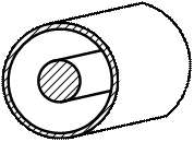
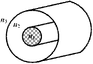
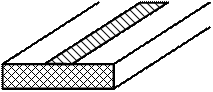
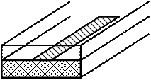
There are many types of transmission lines, some examples of which are shown in Fig. 1.1. The various line types are used for different applications in specific frequency ranges. Striplines and microstrips are used only inside devices, such as amplifiers or filters, and their lengths never exceeds some centimeters. Twisted pairs and coaxial cables are used for cabling a building but coaxial cables can also be used for intercontinental communications. Waveguides are used to deliver large amounts of microwave power over short to moderate distance. Waveguides can also be made of dielectric materials only, as in the case of optical fibers.

a b c
d e
Fig. 1.1. Examples of transmission lines: (a) coaxial cable, (b) two wire line, (c) optical fiber, (d) microstrip, (e) stripline.
Long line – regular transmission line of length greater than of wave in line λ.
Two round conductors (wires) will be assumed to be perfect (i. e. have infinite conductivity). Peculiarity of long line is interference of incident from a generator and reflected from a load EMW. These waves have opposite directions.
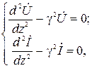
Line has next parameters (distributed):
 [Ω/m] – resistance;
  [1/Ωm] – conductivity;
  [H/m] – inductance;
  [E/m] – capacity.
Equivalent circuit of line element dz is shown in Fig. 1.2.
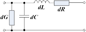
Fig. 1.2
and values depend on wire material and dielectric quality. and are defined by form and dimensions of conductor’s cross-section and distance between them.
Equivalent circuit is fair for symmetric and asymmetric transmission lines.
Parameters of length element dz
 (1.1)
(1.1)
where , , , – line parameters (along 1 meter).
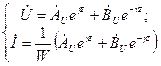
Current and voltage increments
 or using (1.1)
where  – line impedance,
  – line admittance.
Whence there are telegrapher’s equations of long line
 (1.2)
(1.2)
Equation show the connection between voltage U and current I in arbitrary section of line.
In order to solve (1.2) let’s find differential by z
 (1.3)
(1.3)
In regular line the line parameters are constant
 (1.4)
(1.4)
Substituting U and I from (1.2) to (1.3) and after transformation will obtain homogeneous equations of long line
 (1.5)
(1.5)
where  – propagation factor of EMW in line.
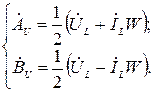
Solution of (1.5)

where  – complex amplitudes of voltage U and current I for incident and reflected waves (
  ,
,  ). If there is “+” in power the wave propagates in negative direction of axis z, “-” – in positive direction.
Propagation factor has complex character  , where α – attenuation factor;
  – phase coefficient; Λ – wave length in line.
Let’s represent  and
and  using values
  and
and  in a line load.
Wave impedance of line  .
.
At this
 (1.6)
(1.6)
For finding the value and using the condition at the line end

From (1.6) at z=0
 (1.7)
(1.7)
Substituting (1.7) in (1.6)
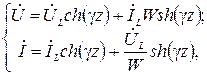 (1.8)
(1.8)
where  – hyperbolic sinus;
  – hyperbolic cosine.
If reflected wave is absent (Fig. 1.3)

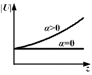
Fig. 1.3
At α>0 part of transferred energy transforms into head. The phase of  delays by linear law (delay from phase of generator).
When reflected wave appears in line without losses (α=0)
 ,
,
where  – complex reflection factor by voltage. It characterizes the matching of the line with the load:
 – there is not reflection (
  ) – transfer wave mode;
 – the wave fully reflected (
  ) – standing wave mode.
There are some cross-sections of the line where  – antinode of field
 .
.
In other case incident and reflected waves are antiphase. Then  – node of field
 .
.
If that and  .
.
Example:
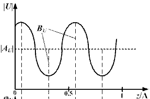
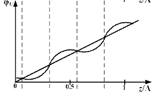
Fig. 1.4
 ;
;
 , [0÷1] – transfer wave factor;
 , [1÷∞] – standing wave factor.
Input impedance  changes as a function of line length. Therefore a line can be treated as impedance transformer.
There are three modes of line work:
1) In TW mode the reflected wave is absent. The wave power fully absorbs in the load.
; ;  .
.
2) In SW mode The wave energy fully reflects from the load and propagates to generator.
;  ;
;  .
.
3) In mixed wave mode  . Part energy is absorbed in the load and part is reflected.
 ;
;  ;
;  .
.
Переглядів: 241